 by
by Pipe wall thickness calculation for your application is very important, In this article we will learn how to select pipe for your application as per ASME code b31.3.
A Pipe or a tube is hollow longitudinal product. ‘A tube’ is a general term used for hollow product having circular, elliptical or square cross -section or for that matter cross section of any closed perimeter.
A pipe is tubular product of circular cross – section that has specific sizes and thicknesses governed by particular dimensional standard.
Thus while tubes can be ordered for any OD or ID or thickness, pipes have specific sizes and thickness and have to be ordered based on these sizes I thickness.
Classification :
Pipes can be classified based on methods of manufacture or based on their applications.
Methods of manufacture :
Seamless pipes are manufactured by drawing or extrusion process. ERW pipes (Electric resistance welded pipes) are formed from a strip which is longitudinally welded along its length. Welding may be by Electric resistance, high frequency, or induction welding. ERW pipes can also be drawn for obtaining required dimensions and tolerance.
Pipes in small quantities are manufactured by EFW (Electric Fusion Welding) process where in instead of electric resistance welding, the longitudinal seam is welded by manual or automatic electric arc process.
There are spiral seam welded pipes. which are large diameter pipes 500 NB and above, and pipes are made by welding a spiral seam produced by forming continuous steel skelp into circular shape.
Centrifugally cast pipes are made by spraying molten metal along a rotating die where the pipes are cast in shape due to centrifugal action.
Classification based on end use :
Pipes are also classified as :
- Pressure pipes or Process pipes
- Line pipes
- Structural pipes.
- Pressure pipes are those which are subjected to fluid pressure and or temperatures. Fluid pressure in generally internal pressure due to fluid being conveyed or may be external pressure. (e.g. jacked piping) and arc mainly used as plant piping.
2. Line Pipes are mainly used for long distance conveying of the fluids and are subjected to fluid pressures. These are generally not subjected to high temperatures.,
3. Structural pipes are not used for conveying fluids and therefore not subjected to fluid pressures or temperatures. They are used as structural components (e.g. Columns, sleeves etc.) and are subjected to static loads only.
Pipes Dimensional Standards :
Diameter : Pipe are designated by Nominal size, Starting from 1/8″ Nominal size, and increasing in steps.
- Pipe sizes increase in steps of 1/8″ for 1/8″ to 1/2″ : 1/8″, 1/4″ 3/8″,l/2″ Normal size.
- Sizes in steps o : 1/4″ : 1/2” 3/4″,1 ” ,1 1/4” 1 1/2″.
- Insteps on 1/2″ up to 4″ : 1 1/2, 2″, 21/2″,3″, 31/2” 4″
- In steps of 1″ up to 6″ :4”, 5″, 6″
- In steps of 2″ up to 36″ : 6″, 8″ 10″ ……etc
Pipe Wall Thickness Calculation Formula
Pipe wall thickness is designed for internal pressure.
When calculating pipe wall thickness operating pressure and operating temperature is always multiplied by factor 1.5 to get design parameter. This factor is called safety factor.
As per clause 304.1.2 (a) of ASME B 31.3, the internal pressure design thickness for straight pipes with t<D/6 can be calculated using the following formula (Equation (3a):

Pipe Wall Thickness Calculation formula
Where,
t = Wall thickness of pipe in mm or inch.
P = Design internal pressure in Mpa or Bar or PSI.
D= Outside diameter of pipe in mm or inch.
We always calculate thickness of pipe on the basis of outside diameter of pipe, rather than inside diameter. This is because the outside diameter of pipe is constant, it is independent of the wall thickness. Outside diameter is taken from American pipe standards.
ASME B36.10 : Welded and Seamless Wrought Steel Pipe.
ASME B36.19 : Stainless Steel Pipes.

Outside diameter of pipe in mm as per ASME B36.10
S=Maximum allowable stress for the material of pipe in Mpa or Bar or KSI.
These are allowable stress values for different materials at different temperatures. Provided in Table A-1 of ASME B31.3. I have included commonly used pipe materials in this calculator. If you want more ASTM materials to be included, please mention in comments section below.
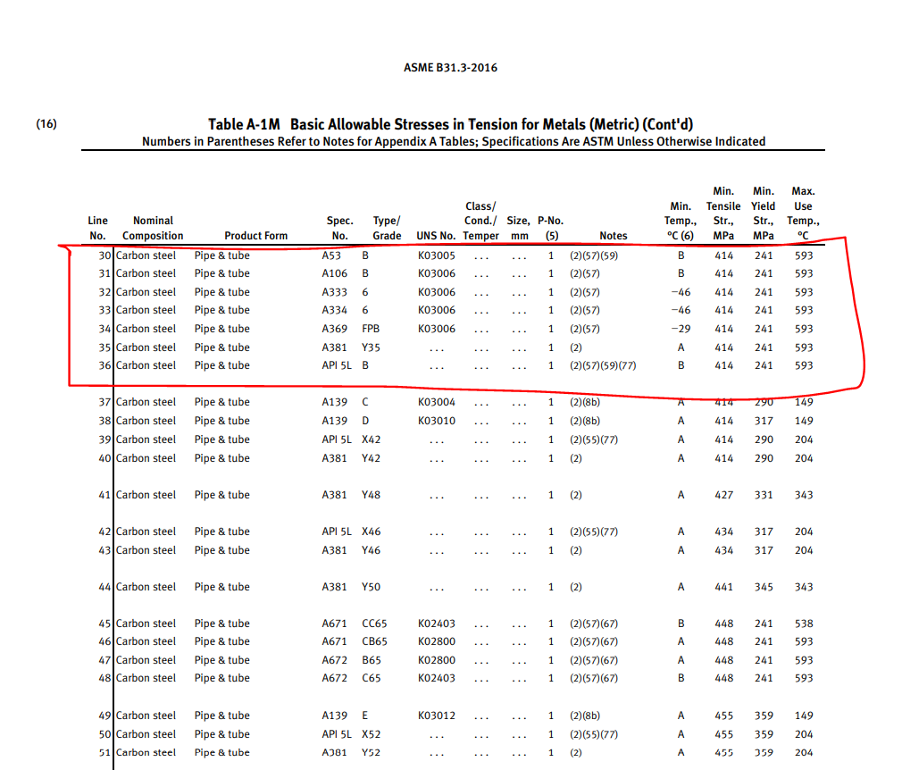

Allowable Stresses in Tension for Metals
E = Weld quality factor.
The value of E, Longitudinal Weld Joint Quality Factor, or Casting Quality Factor can be found in Table A-1A or Table A-1B of the ASME B31.3.
For seamless pipe it is always 1.
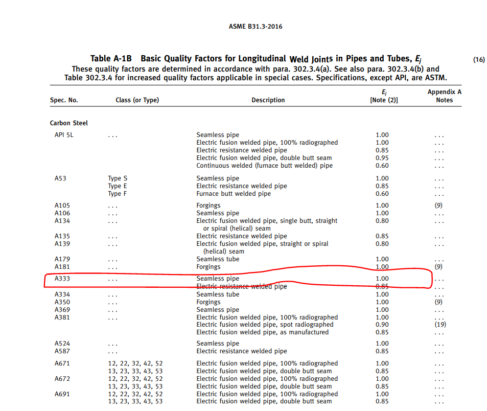
Quality Factors for Longitudinal Weld Joints in Pipes and Tubes
W = Weld strength reduction factor.
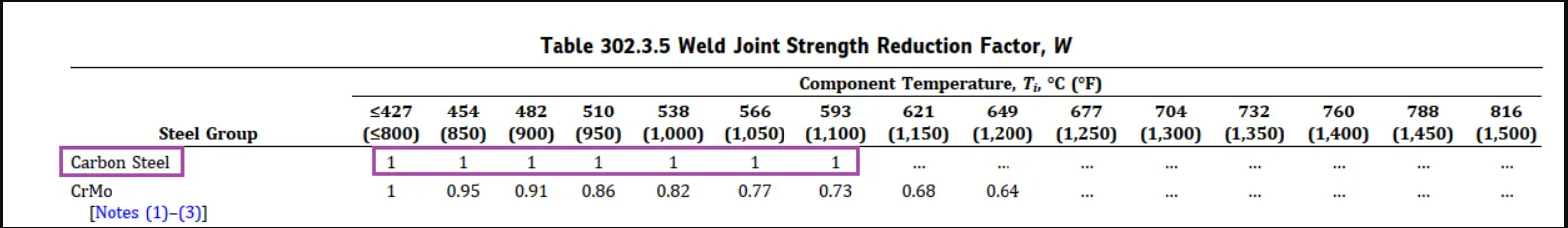
Weld-Joint-Strength-Reduction-Factor
Y = Coefficient of material used.
Valid for t < D/6 and for materials shown. The value of Y may be interpolated for intermediate temperatures.

Values of Coefficient Y
Input required
1.Pipe nominal diameter.
2.Pipe material
3.Pipe manufacturing type: ERW, Seamless etc.
4.Design pressure and temperature.
5.Corrosion allowance for material as per operating condition.
Pipe wall thickness calculation practical example
Inputs
Material -A333
Pressure – 100 Bar
Corrosion and erosion allowance – 3mm
Nominal pipe size – 6″
Mill tolerance 12.50% of the thickness
Design temperature – 200 ºC
Manufacturing type of pipe – Seamless
Pipe wall thickness calculations steps
Step :1 Put the given input data and data from standard catalogue into given formula.
Pressure is 100 bar equal to 10 Mpa and Pipe 6″ is equal to 168.3 mm outer diameter as per ASME B36.1.
Maximum allowable stress at 200 ºC for A333 is S=138 Mpa.
For seamless pipe weld efficiency factor always one i.e E=1. and Y=0.4 for ferritic steel below 450 ºC
Now we have,
t = (10*168.3)÷{2(138*1*1+10*0.4)}
t=5.92mm
Step : 2 Add the corrosion allowance to the calculated thickness.
tc = t+3
=5.92+3
tc=8.92mm
Step 3. Add the mill tolerance to the thickness after adding corrosion value.
tm = tc + 12.50 % of the pipe thickness
tm =tc/0.875 =8.92/0.875 = 10.2 mm (This is required thickness)
Pipe thickness calculator.
You also like to read:
- Mechanical design engineer interview questions and answers for freshers.
- Mechanical engineering interview questions and answers for freshers.
- Top 30 HR interview questions and answers for freshers all jobs.
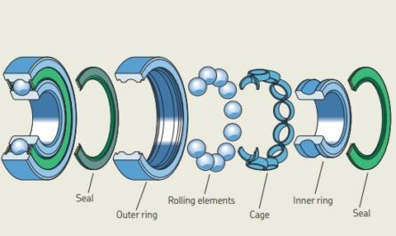
- How to select right bearing for your application.
- Catia v5 interview questions and answers.
Hello thank you for the tutorial. It was very clear and precise. I just want to ask if I could get a copy of the all the tables that you have used. I will be using it for my project on measuring the flowmeter of various pumps in a company here in the Philippines. Thank you in advance!
Hi Mark,
All the table you can get from ASME 31.3, just google ASME 31.3 and you can easily find them in pdf.
Hamood