 by
by If you have done mechanical engineering degree or diploma and looking for any mechanical engineering job. Then this article definitely will help you to prepare and face interview. This article is about mechanical design interview questions and answers for freshers and experienced.This questions are frequently asked in mechanical design engineer interview.
Q.1 What is machine design?
Ans:
This is the first question asked as a mechanical design engineer .Machine design is defined as the use of scientific principles, technical information’s and imagination in the description of a machine or mechanical system to perform specific function with maximum economy and efficiency.
Or
Machine design is the creation of new and better machines and improving the existing ones. A new or better machine is one which is more economical in the overall cost of production and operations.
Q.2 What are the general considerations in machine design?
Ans:
1. Type of load and stresses caused by the load.
- Motion of the parts or kinematics of the machine.
- Selection of materials.
- Form and size of the parts.
- Frictional resistance and lubrication.
- Convenient and economical features.
- Use of standard parts
- Safety of operation.
- Cost of construction.
- Assembling.
Q.3 What is the general procedure in machine design?
Ans:
- Recognition of need. First of all, make a complete statement of the problem, indicating the need, aim or purpose for which the machine is to be designed.
- Synthesis (Mechanisms). Select the possible mechanism or group of mechanisms which will give the desired motion.
- Analysis of forces. Find the forces acting on each member of the machine and the energy transmitted by each member.
- Material selection. Select the material best suited for each member of the machine.
- Design of elements (Size and Stresses). Find the size of each member of the machine by considering the force acting on the member and the permissible stresses for the material used. It should be kept in mind that each member should not deflect or deform than the permissible limit.
- Modification. Modify the size of the member to agree with the past experience and judgment to facilitate manufacture. The modification may also be necessary by consideration of manufacturing to reduce overall cost.
- Detailed drawing. Draw the detailed drawing of each component and the assembly of the machine with complete specification for the manufacturing processes suggested.
- Production. The component, as per the drawing, is manufactured in the workshop.
Q.4 What is the difference between fundamental and derived units?
Ans:
- Fundamental Units: The measurement of physical quantities is one of the most important operations in engineering. Every quantity is measured in terms of some arbitrary, but internationally accepted units, called fundamental units.
- Derived Units: Some units are expressed in terms of other units, which are derived from fundamental units, are known as derived units e.g. the unit of area, velocity, acceleration, pressure, etc.
Q.5 What is the difference between mass and weight?
Ans:
Mass:It is the amount of matter contained in a given body and does not vary with the change in its position on the earth’s surface. The mass of a body is measured by direct comparison with a standard mass by using a lever balance.
Weight:It is the amount of pull, which the earth exerts upon a given body. Since the pull varies with the distance of the body from the center of the earth, therefore, the weight of the body will vary with its position on the earth’s surface (say latitude and elevation). It is thus obvious, that the weight is a force.
Q.6 What are the three laws of motion?
Ans:
- Newton’s First Law of Motion. It states, “Every body continues in its state of rest or of uniform motion in a straight line, unless acted upon by some external force”. This is also known as Law of Inertia.
- Newton’s Second Law of Motion. It states, “The rate of change of momentum is directly proportional to the impressed force and takes place in the same direction in which the force acts”.
- Newton’s Third Law of Motion. It states, “To every action, there is always an equal and opposite reaction”.
Q.7 What is the density of steel and aluminium?
Ans:
Steel – 7850 kg/m^3
Aluminium – 2700 kg/m^3
Wrought iron- 7780 kg/m^3
Copper – 8900 kg/m^3
Cobalt – 8850 kg/m^3
Tungsten – 19 300 kg/m^3
Q.8 Classify engineering materials?
Ans: The engineering materials are mainly classified as:
- Metals and their alloys, such as iron, steel, copper, aluminium, etc.
- Non-metals, such as glass, rubber, plastic, etc.
The metals may be further classified as:
(a)Ferrous metals, and (b) Non-ferrous metals.
The ferrous metals are those which have the iron as their main constituent, such as cast iron, wrought iron and steel.
The non-ferrous metals are those which have a metal other than iron as their main constituent, such as copper, aluminium, brass, tin, zinc, etc.
Q.9 What is heat treatment of steel? What is its purpose?
Ans: Heat treatment is operation or a combination of operations, involving the heating and cooling of a metal or an alloy in the solid state for the purpose of obtaining certain desirable conditions or properties without change in chemical composition. The aim of heat treatment is to achieve one or more of the following objects:
- Increase the hardness of metals.
- Relieve the stresses set up in the material after hot or cold working.
- Improve machinability.
- Soften the metal.
- Modify the structure of the material to improve its electrical and magnetic properties.
- Change the grain size.
- Increase the qualities of a metal to provide better resistance to heat, corrosion and wear.
Following heat treatment processes commonly employed in engineering practice:
- Normalising
- Annealing
- Tempering
- Hardening
- Case hardening
Q.10 Tell me aluminium alloys?
Ans: 1. Duralumin, 2.Y-alloy, 3.Magnalium, 4.Hindalium.
Q.11 What is gun metal?
Ans: It is an alloy of copper, tin and zinc. It usually contains 88% copper, 10% tin and 2% zinc. This metal is also known as Admiralty gun metal. The zinc is added to clean the metal and to increase its fluidity.
Q.12 What are bearing metals and what should be their mechanical properties?
Ans:
Metals- 1. Copper-base alloys, 2. Lead-base alloys, 3. Tin-base alloys, and 4. Cadmium-base alloys.
A bearing material should have the following properties:
- Low coefficient of friction.
- Good wearing qualities.
- Ability to withstand bearing pressures.
- Ability to operate satisfactorily with suitable lubrication means at the maximum rubbing speeds.
- A sufficient melting point.
- High thermal conductivity.
- Good casting qualities.
- Minimum shrinkage after casting.
- Non-corrosive properties.
- Economical in cost.
Q.12 What is fit?
Ans: According to mechanical design,The degree of tightness or looseness between the two mating parts is known as a fit of the parts.
Q.13 What are the types of fits?
Ans:
- Clearance Fit- In a clearance fit, the tolerance zone of the hole is entirely above the tolerance zone of the shaft. In a clearance fit, the difference between the minimum size of the hole and the maximum size of the shaft is known as minimum clearance whereas the difference between the maximum size of the hole and minimum size of the shaft is called maximum clearance.
- Interference Fit– In an interference fit, the tolerance zone of the hole is entirely below the tolerance zone of the shaft. In an interference fit, the difference between the maximum size of the hole and the minimum size of the shaft is known as minimum interference, whereas the difference between the minimum size of the hole and the maximum size of the shaft is called maximum interference.
- Transition Fit- In a transition fit, the tolerance zones of hole and shaft overlap. The transition fits may be force fit, tight fit and push fit.
Q.14. For Example, The dimensions of the mating parts, according to basic hole system, are given as follows: Hole: 25.00 mm 25.02 mm Shaft: 24.97 mm 24.95 mm Find the hole tolerance, shaft tolerance and allowance?
Ans: Hole tolerance
We know that hole tolerance = Upper limit of hole – Lower limit of hole
= 25.02 – 25 = 0.02 mm
Shaft tolerance We know that shaft tolerance = Upper limit of shaft – Lower limit of shaft
= 24.97 – 24.95 = 0.02 mm
Allowance We know that allowance = Lower limit of hole – Upper limit of shaft
= 25.00 – 24.97 = 0.03 mm
Q.15 What is the difference between stress and strain?
Ans:
Stress:
When some external system of forces or loads act on a body, the internal forces (equal and opposite) are set up at various sections of the body, which resist the external forces. This internal force per unit area at any section of the body is known as unit stress or simply a stress.
It is denoted by a Greek letter sigma (σ). Mathematically,
Stress, σ = P/A
where P = Force or load acting on a body, and A = Cross-sectional area of the body.
In S.I. units, the stress is usually expressed in Pascal (Pa) such that 1 Pa = 1 N/m2.
In actual practice, we use bigger units of stress i.e. megapascal (MPa) and gigapascal (GPa), such that
1 MPa = 1 × 10⁶ N/m2
= 1 N/mm2 and 1 GPa
= 1 × 10⁹ N/m2 = 1 kN/mm2
Strain:
When a system of forces or loads act on a body, it undergoes some deformation. This deformation per unit length is known as unit strain or simply a strain. It is denoted by a Greek letter epsilon (ε). Mathematically,
Strain, ε = δl / l or δl = ε.l where
δl = Change in length of the body, and l = Original length of the body.
Q.16 What is factor of safety and give its formulas for various materials?
Ans: It is in general, as the ratio of the maximum stress to the working stress. Mathematically, Factor of safety = Maximum stress ÷Working or design stress
In case of ductile materials e.g. mild steel, where the yield point is clearly defined, the factor of safety is based upon the yield point stress
And it is ,
Factor of safety = Yield point stress ÷Working or design stress
In case of brittle materials e.g. cast iron, the yield point is not well define as for ductile materials. Therefore, the factor of safety for brittle materials is based on ultimate stress. ∴
Factor of safety = Ultimate stress ÷Working or design stress.
Q.17 What are the different types of mechanical joints?
Ans: 1.Rivet joint
2.Flange Joint
3.Spigot and socket joint
4.Welded Joints – a. Lap joint, b. Butt Joint
5.Bolted Joint
6.Screw Joint
7.Cotter and Knuckle Joint.
Q.18 What are the different types of welding processes?
Ans: 1. Fusion Welding
- Thermit Welding
- Gas Welding
- Electric Arc Welding
- Forge Welding
Q.19 What are the different types of keys and couplings?
Ans: 1. Sunk keys, 2. Saddle keys, 3. Tangent keys, 4. Round keys, and 5. Splines.
-
Rigid coupling.
It is used to connect two shafts which are perfectly aligned. Following types of rigid coupling are important from the subject point of view:
(a) Sleeve or muff coupling. (b) Clamp or split-muff or compression coupling, and (c) Flange coupling.
Flexible coupling-
It is used to connect two shafts having both lateral and angular misalignment. Following types of flexible coupling are important from the subject point of view:
(a) Bushed pin type coupling, (b) Universal coupling, and (c) Oldham coupling.
Q.20 What are the factors considered while selecting belt drive?
Ans:
- Speed of the driving and driven shafts,
- Speed reduction ratio,
- Power to be transmit,
- Center distance between the shafts,
- Positive drive requirements,
- Shafts layout,
- Space available,
- Service conditions.
Q.21 What are the types of belts?
Ans: 1. Flat belt, V belt and Circular or Rope.
Q.22 What is mechanical design engineering tolerance?
Ans: Tolerance is allowable variation for any given size or the total amount by which a given dimension may vary in order to achieve proper function of product.
Tolerance for hole = Hole (MMC)- Hole (LMC)
Q.23 Why tolerances are required?
Ans: According to mechanical design, The production of closely mating parts, with very small tolerances is theoretically possible, but economically its unfeasible as this will increase rejection rate and high precise tools and workforce will be required.so that deviation is required in parts.
Q.24 What do you understand by engineering drawings?
Ans: Engineering drawing a type of technical document used to transfer technical information, to define requirements. Or its graphical language that communicates ideas and information from one mind to another.
Q.25 What is section, Projection, Isometric & Detailed View?
Ans:
- Projection View: Orthographic Projection view is use for representing three dimensional objects in two dimensions.
- Section View: It is use to show interior construction of parts in engineering drawing.
- Isometric View: Isometric projections represents 3-Dimensional objects into 2 Dimensional in engineering drawings. In these three co- ordinate axes appear equally foreshortened and the angle between any two axes is 120 degree.
- Detailed view: It represents the larger view of any section of engineering drawing.
Q.26 What is the symbol of first angle and third angle projection?
Ans:
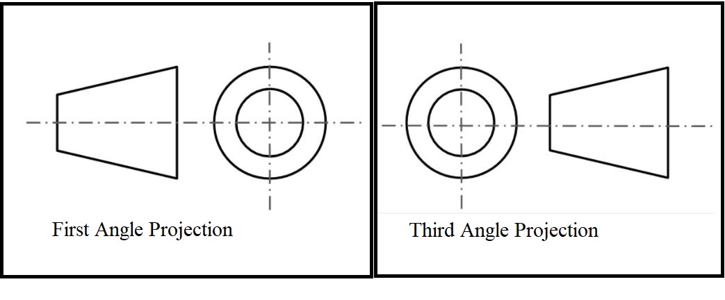
Q.27 What are types of projections used to make engineering drawings?
Ans: 1. First angle projections
2.Second angle projections
Q.28 What is least count and how to calculate least count?
Ans:
It is the smallest value that can be measured by the measuring instrument.
Least count = Value of main scale division – Total number of vernier scale division
Q.29 What is the least count for normal scale, vernier and Micrometre?
Ans:
Normal scale – Minimum distance measured by normal scale is 1 mm so that least count is 1 mm.
Least count of vernier caliper:
=Smallest reading on main scale ÷ No of divisions on vernier scale
=1/10
=0.1 mm so that vernier have least count 0.1 mm
Micrometre may have 0.01 mm least count.
Q.30 Draw stress strain curve for brittle and ductile materials?
Ans: As a mechanical design engineer you must know the basic behavior of brittle and ductile materials.

Thank you for reading interview questions and answers for mechanical design engineers.
You also like to read:
1.Solid edge interview questions and answers.
2.Mechanical design engineer interview questions and answers for freshers.
3.Mechanical engineering interview questions and answers for freshers.
4.Top 30 hr interview questions and answers for freshers all jobs.
5.How to select right bearing for your application.
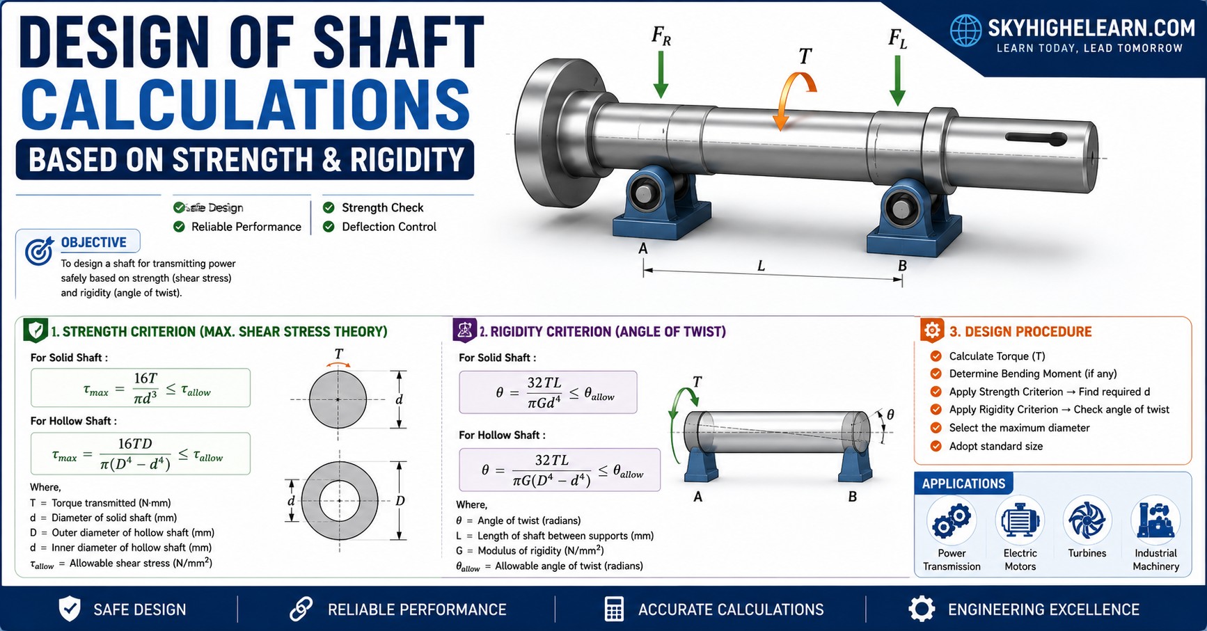
6.Design of mechanical shaft procedure.

thanks for sharing such info
I just found the info which I am searching for a long time so I am thankful to you thanks.keep up such great job
Thanks for sharing this information
amazing sir ji thanks for sharing profitable knowledge
nice post !!! Good Information thanks ….
Thank you so much for your great post. I think it is most helpful for everyone. It is great post for Machanical learner