 by
by Design of mechanical shaft procedure. In this article we have cleared general procedure of design of mechanical shaft.
- Determine the rotational speed of the mechanical shaft.
- Calculate the power or the torque to be transmitted by the shaft.
- Determine the design of the power-transmitting components or other devices that will be mounted on the shaft, and specify the required location of each device.
- Specify the location of bearings to support the shaft. Normally two and only two bearings are used to support a shaft. The reactions on bearings supporting radial loads are assumed to act at the midpoint of the bearings.
For example, if a single row ball bearing is used, the load path is assumed to pass directly through the balls. If thrust (axial) loads exist in the shaft, you must specify which bearing is to be designed to react against the thrust load. Then the bearing that does not resist the thrust should be permitted to move slightly in the axial direction to ensure that no unexpected and undesirable thrust load is exerted on that bearing.
Bearings should be placed on either side of the power-transmitting elements if possible, to provide stable support for the shaft and to produce reasonably well-balanced loading of the bearings. The bearings should be placed close to the power-transmitting elements to minimize bending moments. Also, the overall length of the shaft should be kept small to keep deflections at reasonable levels.
You also like to read:
1.Solid edge interview questions and answers.
2.Mechanical design engineer interview questions and answers for freshers.
3.Mechanical engineering interview questions and answers for freshers.
4.Top 30 hr interview questions and answers for freshers all jobs.
5.How to select right bearing for your application.
6.Design of mechanical shaft procedure.
- Propose the general form of the geometry for the shaft, considering how each element on the shaft will be held in position axially and how power transmission from each element to the shaft is to take place.
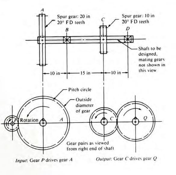
For example, consider the shaft in Figure 1, which is to carry two gears as the intermediate shaft in a double-reduction, spur gear type speed reducer. Gear A accepts power from gear P by way of the input shaft. The power is transmitted from gear A to the shaft through the key at the interface between the gear hub and the shaft. The power is then transmitted down the shaft to point C, where it passes through another key into gear C.
Gear C then transmits the power to gear Q and thus to the output shaft. The locations of the gears and bearings are dictated by the overall configuration of the reducer. It is now decided that the bearings will be placed at points B and D on the shaft to be designed. But how will the bearings and the gears be located so as to ensure that they stay in position during operation, handling, shipping, and so forth of course, there are many ways to do this.
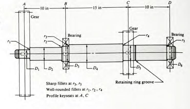
One way is proposed in Figure 2. Shoulders are to be machined in the shaft to provide surfaces against which to seat the bearings and the gears on one side of each element. The gears are restrained on the other side by retaining rings snapped into grooves in the shaft. The bearings will be held in position by the housing acting on the outer races of the bearings. Key seats will be machined in the shaft at the location of each gear. This proposed geometry, provides for positive location of each element.
- Determine the magnitude of torque that the shaft sees at all points. It is recommended that a torque diagram be prepared.
- Determine the forces that are exerted on the shaft, both radially and axially. Resolve the radial forces into components in perpendicular directions, usually vertically and horizontally.
- Solve for the reactions on all support bearings in each plane.
10.Produce the complete shearing force and bending moment diagrams to determine the distribution of bending moments in the shaft.
11.Select the material from which the shaft will be made, and specify its condition: cold-drawn, heat-treated, and so on. Plain carbon or alloy steels with medium carbon content are typical, such as AISI1040, 4140, 4340, 4640, 5150, 6150, and 8650. Good ductility with percent elongation above about 12% is recommended. Determine the ultimate strength, yield strength, and percent elongation of the selected material.
- Determine an appropriate mechanical shaft design stress, considering the manner of loading (smooth, shock, repeated and reversed, or other).
- Analyse each critical point of the shaft to determine the minimum acceptable diameter of the shaft at that point in order to ensure safety under the loading at that point. In general, the critical points are several and include those where a change of diameter takes place, where the higher values of torque and bending moment occur, and where stress concentrations occur.
14.Specify the final dimensions for each point on the shaft. Normally, the results from Step 13 are used as a guide, and convenient values are then chosen. Design details such as tolerances, fillet radii, shoulder heights, and key seat dimensions must also be specified. Sometimes the size and the tolerance for a shaft diameter are dictated by the element to be mounted there.
For example, ball bearing manufacturers’ catalogues specify limits for bearing seat diameters on shaft.

Naujausios žiniatinklio naujienos realiuoju laiku