 by
by Shaft is used for the transmission of torque and bending moment. Various transmitting elements are mounted on it, so that design of shaft is critical part of any power transmission system.
1. Shaft
Virtually all machines involve the transmission of motion or power from input source to desired output source. Usually an electric motor or Internal combustion engine is the input source which transmits the power to the input shaft by coupling or gears or belt. The shaft is the rotating long cylindrical element supported by bearings and loaded torsional, axially or transversely as the machine operates. Most of the time power transmission shafts are cylindrical but in special applications it may be rectangular, square, hexagonal or any other cross section. Shaft can carry pulleys, gears, belts or sprockets to transmit power and motion or simply connect with other shaft by coupling.
1.1 Shaft types.
1.Transmission Shaft – Which carries machine elements likes gears, pulleys.
2.Machine shaft – It is the shaft which is an integral part of the machine.
1.2 Manufacturing of shaft
Generally, shafts are manufactured by a hot rolling process which has low dimensional accuracy, finished by turning and grinding. The cold rolled shafts are stronger and accurate than hot rolled shafts but they have highly residual stresses. The residual stresses may cause distortion of the shaft when it is machined, especially when slots are cut.
1.3 Shaft material and standard sizes of transmission shafts
The material used for the shaft should have high strength, good machinability, high wear resistance and good heat treatment properties. Typically, carbon steel of grades 40 C 8, 45 C 8, 50 C 12 and 50 C 4 are in use. When a shaft of high strength is required then material is alloy steel.
6mm to 22 mm with 2 mm steps
25 mm to 80 mm with 5 mm steps
80 mm to 120 mm with 10 mm steps
120 mm to 500 mm with 20 mm steps
The standard length of the shafts are 5 meter, 6 meter and 7 meter.
1.4 Maximum permissible stresses for the design of shaft
1.Permissible or allowable tensile stress (σt )
σt = 0.6 σel or 0.36 σu, consider whichever is less.———-(eq.1)
Where,
σel = Yield strength or elastic limit
σu = Ultimate tensile strength(N/mm^2)
2. Permissible or allowable shear stress (τ max)
τ max = 0.3 σel or 0.18 σu, consider whichever is less.———-(eq.2)
2. Design of shaft based on
- Strength
- Rigidity
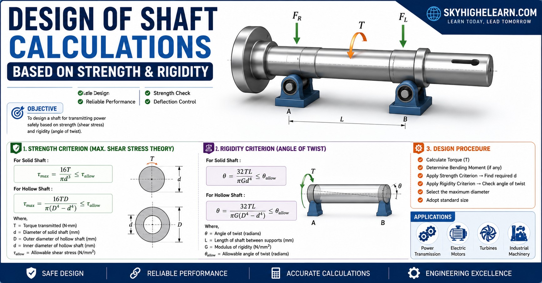
2.1 Design of shaft based on strength
Shafts are subjected to axial tensile force, torsional moment or bending moment or their combinations. Most of the transmission shafts are subjected to combined torsional and bending moments. The design of the transmission shaft consists of determining the correct shaft diameter from strength and rigidity considerations.
Following cases may be considered while designing of shaft on the basis of strength,
It subjected to
1.Twisting moment or torque only
2.Bending moment only
3.Combine twisting and bending moment
2.1.1 Design of shaft when subjected to pure torsional moment or torque only
$$\tau\;max=\frac{16T}{\mathrm{πd}^3}$$-(eq.3)
Where
τ max = Maximum permissible or allowable shear stress of the material in N/mm²
T= Torsional moment or Torque in N.mm
For example : A transmission shaft rotating at 250 rpm. is to transmit 5kW. Assume shaft is
to be made of plain carbon steel(30C8). Determine the diameter of the shaft, neglect the bending moment on the shaft.
Lets,
Yield strength of 30C8 (σel)= 400 N/mm²; Power (P) = 5kW=5000W; Speed (N) = 250 rpm
we know that P=2πNT/60
5000 = 2π*250*T/60
T=190.985 Nm = 190985 N.mm
τ max = 0.3*400———- from (eq.2)
=120 N/mm²
by using (eq.3) we have,
120 =16 x 190985/πd³
d= 20.091 mm
2.1.2 Design of shaft when subjected to pure bending moment only
$$\sigma b=\frac{32M_b}{\mathrm{πd}^3}$$-(eq.4)
Where,
M = Maximum bending moment in N.mm
σb = Allowable or permissible bending stress (tensile or compressive) in N/mm²
For example: A pair of wheels of a railway wagon carries a load of 20 kN on each axle box,
acting at a distance of 150 mm outside the wheel base. The gauge of the rails is 1.8 m. Find the
diameter of the axle between the wheels, if the stress is not to exceed 85 N/mm².
lets,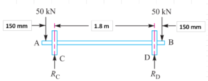
W= 20kN = 20000N; σb = 85 N/mm²; L = 150 mm; x = 1.8m = 1800 mm.
Maximum bending moment M = W * L = 20000 * 150 = 3000000 N.mm
from (eq. 4)
85 = 32 * 3000000 /πd³
d = 71.1171 mm
2.1.3 Design of shaft when combined bending and twisting moment
When the shaft is subjected to combined twisting bending moment, then the shaft must be designed on the
basis of combine moments.
Various theories of failures suggest to account for the elastic failure of the materials when
they are under both twisting and bending stresses.
1. Maximum shear stress theory (Guest’s theory).
Always used for ductile materials( for example. mild steel).
$$\tau\;max=\frac{16}{\mathrm{πd}^3}\sqrt{{(M_b)}^2+{(M_t)}^2}$$
According to maximum shear stress theory,
Yield strength in shear = 0.5 * Yield strength in tension or compression.
$$S_{sy}=0.5\times S_{yt}$$
Allowable value for maximum shear stress is ,
$$\tau_{max}=\frac{S_{sy}}{fos}=\frac{0.5S_{yt}}{fos}$$
Equivalent Torsional Moment:
The expression for equivalent torsional moment is $$Te=\sqrt{{(M_b)}^2+{(M_t)}^2}$$. It is the moment, which when acting alone, will produce the same torsional shear stress in the shaft as under the combined action of bending moment (Mb) and torsional moment (Mt).
2. Maximum normal stress or principal stress theory (Rankine’s theory).
Always used for brittle materials (for example. cast iron).
$$\sigma1=\frac{16}{\mathrm{πd}^3}\lbrack M_{b+}\sqrt{{(M_b)}^2+{(M_t)}^2}\rbrack$$
According to maximum principal stress theory, Permissible value of maximum principal stress is,
$$\sigma1=\frac{S_{yt}}{fos}$$
Equivalent Bending Moment:
The expression for equivalent bending moment is $$\lbrack M_b+\sqrt{{(M_b)}^2+{(M_t)}^2}\rbrack$$.It is the moment, which when acting alone, will produce the same bending stresses (tensile and compressive) in the shaft as under the combined action of bending moment (Mb) and torsional moment (Mt).
The concept of equivalent torsional moment is used in the design of shafts on the basis of maximum shear stress theory of failure. The concept of equivalent bending moment is used in the design of shafts on the basis of maximum principal stress theory of failure.
2.2 Design of shaft based on Rigidity.
Shaft design is based on lateral rigidity and Torsional rigidity.
If transmission shaft does not twist too much under the action of external torque then it is on the basis of torsional rigidity.It is important in case of camshaft of IC engine is important where valve timing is important. The permissible amount of twist should not exceed 0.25° per meter length of the shaft whereas for line shaft it is about 2.5 to 3°.
Similarly, if transmission shaft does not deflect too much under the action of bending moment and external forces. It is important in transmission shaft and shaft running at high speeds.
The angle of twist θ(in radians) $$\theta_r=\frac{M_t\times l}{GJ}$$
Convert θr to θ° $$\theta=\frac{180}{\mathrm\pi}\times\frac{M_tl}{GJ}$$
For circular solid shaft, $$J=\frac{\mathrm{πd}^4}{32}$$
Final equation, $$\theta=\frac{584\;M_t\;l}{Gd^4}$$
Where,
θ = Angle of twist (deg)
l = Length of shaft subjected to twisting moment (mm)
Mt = Torsional moment (N.mm)
G = Modulus of rigidity (N/mm^2)
d= Diameter of the shaft (mm)
You also like to read:
1.Solid edge interview questions and answers.
2.Mechanical design engineer interview questions and answers for freshers.
3.Mechanical engineering interview questions and answers for freshers.
4.Top 30 hr interview questions and answers for freshers all jobs.
5.How to select right bearing for your application.
6.Design of mechanical shaft procedure.